- Remove the operation panel unit. (Refer to "Operation Panel (PCB13)", "Replacement and Adjustment" in Main Chapters.)
Remove the bottom cover [A] (
 ×4).
×4).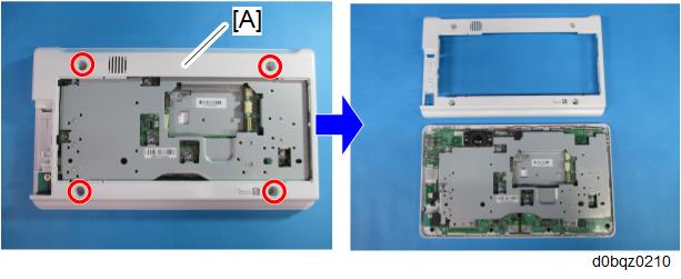

- There are ten hooks inside the operation panel unit. Before removing the operation panel bottom cover, check the photos below.
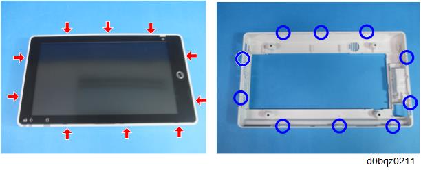
- There are ten hooks inside the operation panel unit. Before removing the operation panel bottom cover, check the photos below.
Remove the base bracket [A].
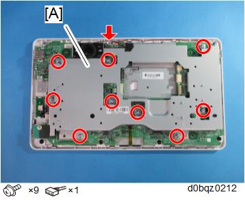
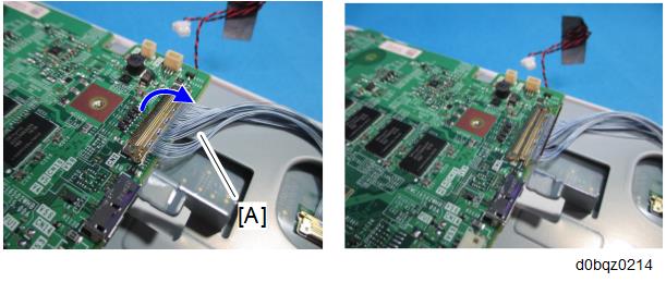
- Remove the main controller board [A].
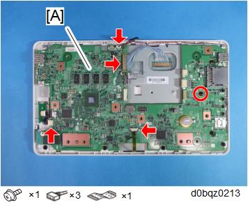
Lift the fastener of the LCD I/F cable [A] on the main controller board side.
- By factory default, the following switches of the DIP switch [A] on the main controller board are set to ON: No.1, No.3, and No.6. When installing the operation panel unit, make sure that the DIP switch setting is correct for the MFP on which you are installing the panel.
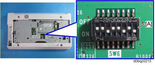
- The correct DIP switch setting depends on the MFP. Note the DIP switch settings of the old operation panel unit before replacing, and apply the same settings to the new Smart Operation Panel.
The following example is for DIP switch settings when the following switches are set to ON: No.1, No.3, and No.6 (this is the factory default setting of a service part).
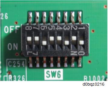
- If the DIP switch setting is wrong, SC672 will be displayed.
- DIP switch No.1 turns ON/OFF the SC reduction function. Change the setting when needed.
- 0 (OFF): The SC is displayed on the operation panel when SC672/SC673 occur.
- 1 (ON): If the error is caused by a software defect when SC672/SC673 occur, automatically reboot is performed and the SC is reset. If the error is caused by a hardware defect when SC672/SC673 occur, the SC is displayed on the operation panel.
- After replacing the main controller board, perform the following checks: