
- When attaching the belt, make sure that there is no foreign material on the roller.
- Make sure to attach the belt with the edge with markings (2 white dots) at the unit’s rear.
- Be careful not to bend or scratch the belt.
- Place the image transfer unit upright with its front face down, and then attach the belt from the top.
Make sure to have the belt’s edge with markings (2 white dots) positioned at the top (unit’s rear).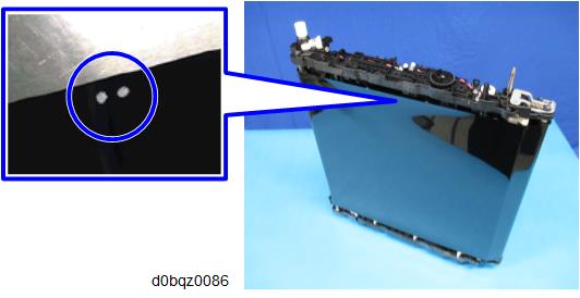
- Holding the resin parts on the top and bottom, place the unit on its side.
- Adjust the belt position according to the following two points:
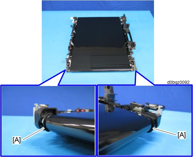
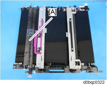
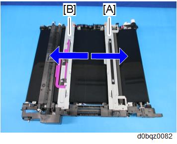
- The belt must be attached between the flanges [A] at both ends of the tension roller.
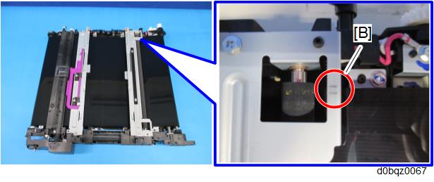
- The belt’s edge must be between the two lines [B] on the frame.
- Apply tension back to normal.
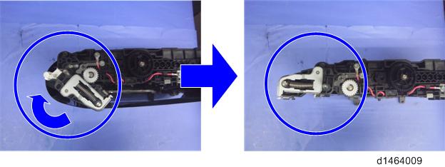
- Rotate the gear to change to the CLOSED position.
The part in the red circle closes.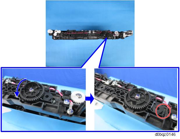
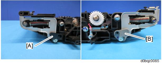
- Attach the tension fixing frames [A] and [B] (front side: black, rear side: gray).
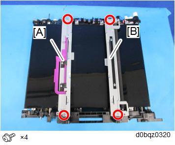
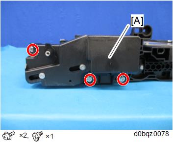
- Attach the bracket [A] and [B].
Put toner on the image transfer belt.
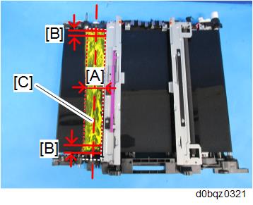
[A]: About 50mm around the Roller [C].
[B]: About 5mm
- It is not necessary to specify the color of the toner, though yellow toner is used in the example above.
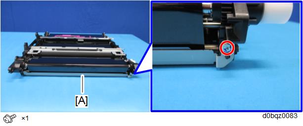
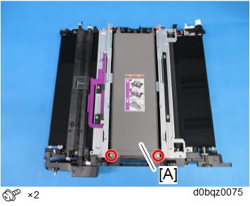
- Attach the image transfer cleaning unit [A].
Rotate the image transfer belt clockwise [A] by approximately 10 mm, and then rotate it counterclockwise [B] through one rotation of the belt. Make sure that the belt has not deviated.
- Attach the bracket [A].
- Attach the image transfer lock unit [A].
Attach the image transfer upper cover [A].
Attach the image transfer front cover, and then install the image transfer unit on the machine.