
- The FFC connector has a lock mechanism. Do not use force to pull it out.
- Remove the controller box cover. (Controller Box Cover)
Remove the controller board (PCB11). (Controller Board (PCB11))
Remove the BICU (PCB10) [A].
Disconnect the upper FFC (scanner) while pressing the lock release button.
Disconnect the lower FFC while pressing the lock release levers on its sides.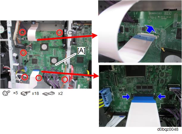

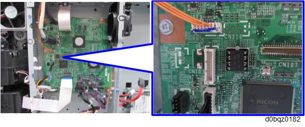
- When replacing the BICU, be sure to remove the EEPROM [A] from the old board and install it on the new board. By doing this, the SP and other settings can be carried across.
Make sure the serial number is input in the machine for the NVRAM data with SP5-811-004, and then turn the main power off/on, if not, SC995-001 occurs.
- For information on how to configure this SP, contact the supervisor in your branch office.
- When replacing the BICU, be sure to remove the EEPROM [A] from the old board and install it on the new board. By doing this, the SP and other settings can be carried across.