Before replacing parts, be sure to turn the main power off and disconnect the power plug from the receptacle.
Checking if the problem reoccurs
- Before replacing the board, cable and operation panel, check if the problem reoccurs.
Disconnecting, reconnecting and replacing the USB cable
- Disconnect and then reconnect both ends of the USB cable and check if the problem persists.
If the problem persists, identify the cause of the problem according to the flowchart.
For information about how to remove and reattach the PCBs, control panel and cables, see Chapter 4 "Replacement and Adjustment".
Replacing DIMM
Unlock the DIMM socket, and then remove the DIMM.
With the locks at the sides of the DIMM socket lowered outward, insert the new DIMM.
Be sure to insert the DIMM vertical to the socket.
Insert the DIMM all the way through until it clicks.
DIMM replacement procedure (excerpts from the manufacturer's specification sheet)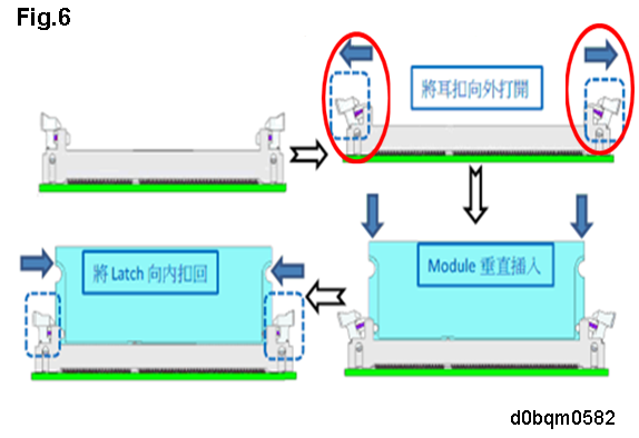
DIMM locking status (A: unlocked, B: locked)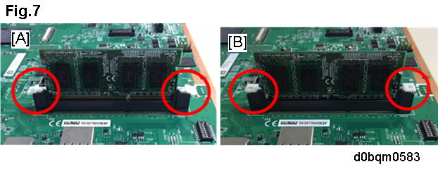
LED/POSTCODE Display
POSTCODE
When the power is tuned on or when the machine recovers from the STR state, the BIOS self-diagnostic code appears.LED after BIOS is completed
POSTCODE1,2,3,4,5,6 Lighting up
POSTCODE7 Lighting up
POSTCODE8 Blinking
In case of DIMM loose connection or BIOS error, POSTCODE 7 does not blink and part or all of the LEDs light up.
Device status and LED indication
Status
LED
BIOS/OS LED (Red)
POST CODE LED(Red)
Normal (at the startup)
Undefined
Undefined
Normal (waiting)
Slow blink (every 1 second)
Slow blink (every 1 second) DIMM error
Off
Part or all LEDs light up.
Controller board error
(BIOS error)
Off
All LEDs light up.
Controller board error
Slow blink (every 1 second)
POST CODE8
Slow blink (every 1 second)
Fig.8: LED area
Fig.9: Normal (waiting) (POSTCODE_8 and BIOS/OS LED blinking every 1 second.)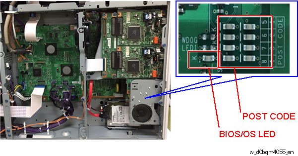
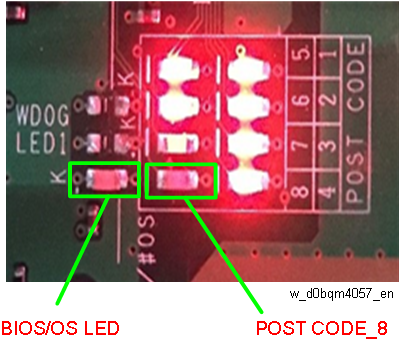
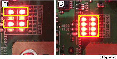
Fig. 10: Error status
[A]: LEDs 1, 3, 5, and 7 light up.
[B]: LEDs 1 to 8 all light up.
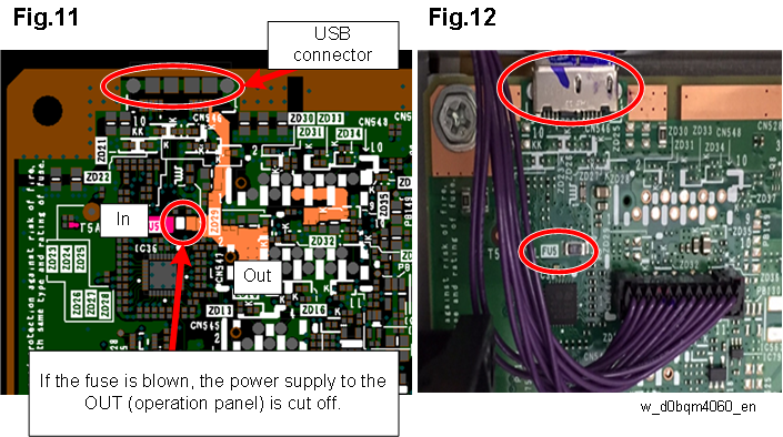
Checking the Fuse
Check the voltage at the OUT (operation panel).