
- When installing this option, turn OFF the main power and unplug the power cord from the wall socket. If installing without turning OFF the main power, an electric shock or a malfunction may occur.

- This option cannot be used together with the following peripherals:
- Internal Shift Tray SH3080 (D3FV)
- Bridge Unit BU3090 (D3FW)
- Internal Finisher SR 3250 (D3FG)
- Side Tray Type M37 (D3FS)
-Internal Multi-Fold Unit FD3010 (D3FS) - For using this option together with "1 Bin Tray BN3130", attach the bottom plate of this option at the beginning, then install the "1 Bin Tray BN3130", followed by installing this option.
Remove the packing tapes and retainers, and then remove the accessories (screws, etc.).
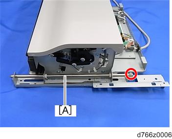
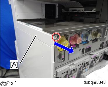
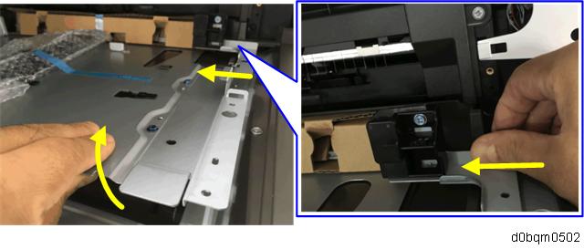
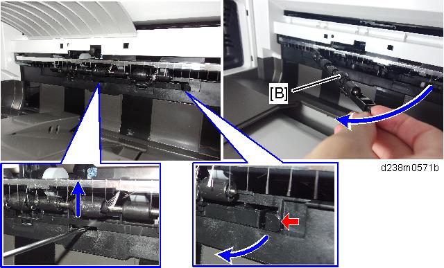
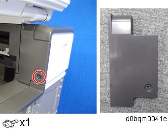
- Remove the knob screw and red tag [A] (
 x 1).
x 1).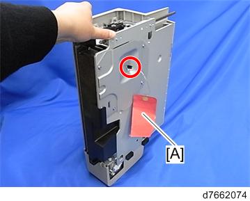
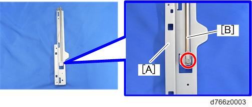
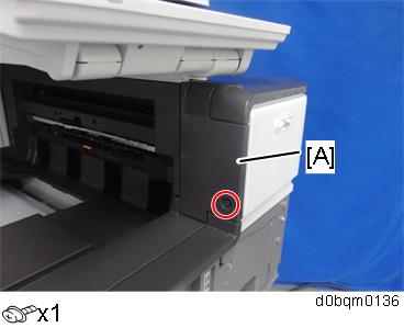
- Remove the shaft [B] from the slide rail [A] ( x 1).
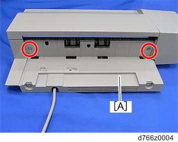
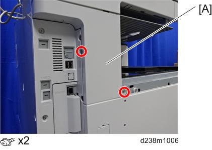
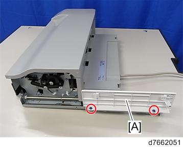
- Remove the paper exit cover [A] ( x 2).
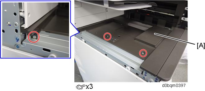
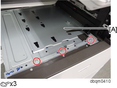
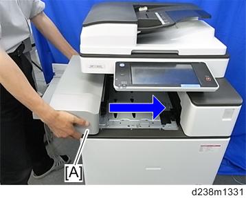
- Place the slide rail [A] under the internal finisher [B].
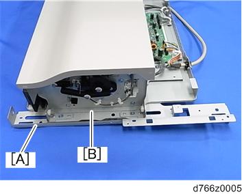
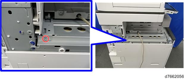
- Insert the shaft [A] into the holes located in the slide rail and internal finisher, and then fasten with the screw ( x 1).
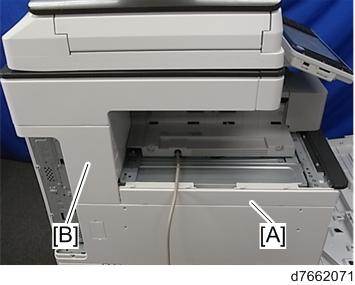
- Attach the paper exit cover (removed in step 4) [A] ( x 2).

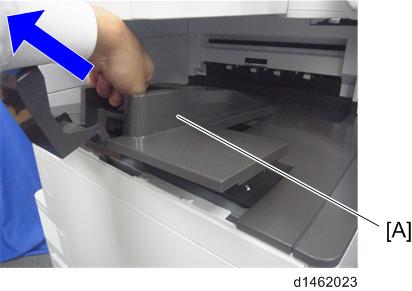
- Remove the paper exit tray [A].
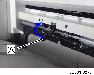
- Remove the paper exit feeler [A].
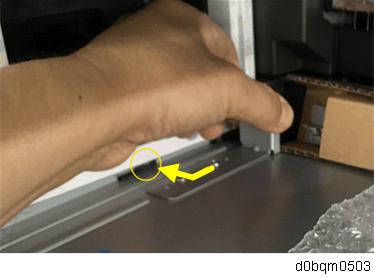
- Tuck in the lever [A] for detecting when the tray is full.
- Open the front cover, and then remove the left upper cover [A].
- Remove the left rear cover [A].
- Remove the proximity sensor left cover [A].
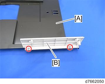
Remove the paper exit lower cover [A].
- The lower inside cover can be removed together with the paper exit lower cover since the inside cover is secured on the paper exit lower cover with two screws.
- Remove the lower inside cover [B] from the paper exit lower cover [A] ( x 2).
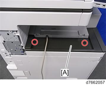
- Insert the bottom plate [A] into the holes.
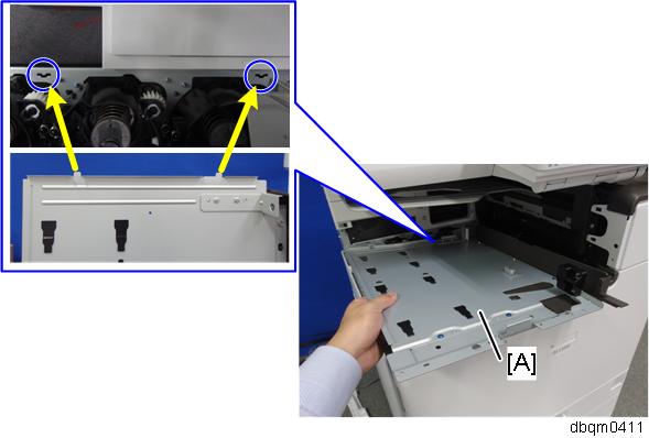
You can easily install the plate as follows:Evenly insert the bottom plate under the upper rear inner cover [B] from the front.
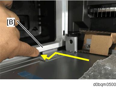
Check that the front resin part of the bottom plate and the paper exit cover are at this location.
Slightly lifting the front right part of the bottom plate, slide the front resin part of the bottom plate under the paper exit cover.
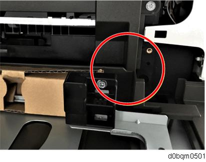
Pulling the bracket at the rear part slightly, engage the hook on the bottom plate with the hole in the side of the machine.
- Install the bottom plate [A] (Accessory No. 7).
- Install the lower inside cover (removed in step 15) [A] in the finisher ( x 2, Accessory No.5).
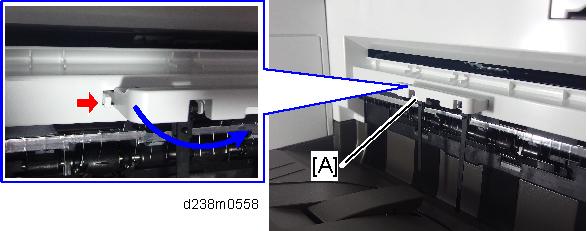
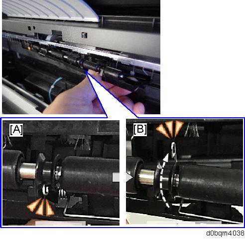
- Remove the driven roller [B] at the machine’s exit tray and attach the supplied driven roller [A].
- Insert a flathead screwdriver into the depression in the center, and then, lifting the driven roller, unlock the part indicated by the red arrow.
- When attaching the driven roller, push its center all the way in until it clicks.
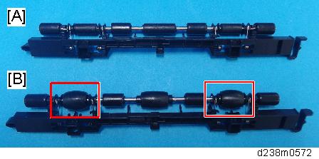
[A]: The supplied driven roller has flat rollers.
[B]: The machine’s standard driven roller has drum-type rollers (as indicated by red frames).
The spring arm on the flat roller might be disconnected due to the vibration or shock. After attaching the roller, perform a visual check whether the state of assembly is normal or not.
[A]: Normal position, [B]: spring arm is disconnected.
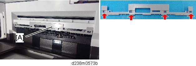
- Attach the paper support guide [A] (Tab x 4).
- Reattach the proximity sensor on the left cover.
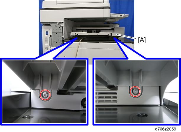
- Install the internal finisher [A].
- Secure the finisher ( x 1, Accessory No.8).
- Reattach the left upper cover [A] and left rear cover [B].
- Attach the left lower cover [A] ( x 2, Accessory No.6).
- Attach the paper exit tray [A] ( x 2, Accessory No.4).
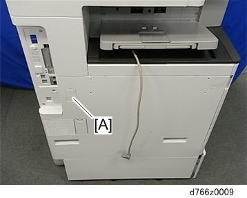
- Remove the Connector cover [A] (Release the tab).
- Connect the interface cable [A].
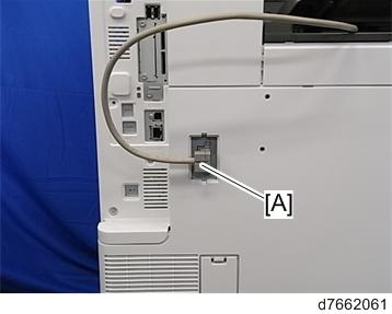
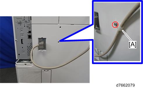
- Attach the nylon clamp [A] as shown below ( x 1, Accessory No.9).
- Turn ON the main power.
- Ensure that the operation panel displays finisher jobs properly and that it works properly.