
- Referring to the following procedure, be sure that there are no mistakes in the mounting position and orientation of the NVRAM.
Incorrect installation of the NVRAM will damage both the controller board and NVRAM. - SC195 (Machine serial number error) will be displayed if you forget to attach the NVRAM.
- Passwords for the Supervisor and Administrator 1 will be discarded later in this procedure.
- The new NVRAM initializes SPs and issues an SC. Reset the SC with the procedure below.
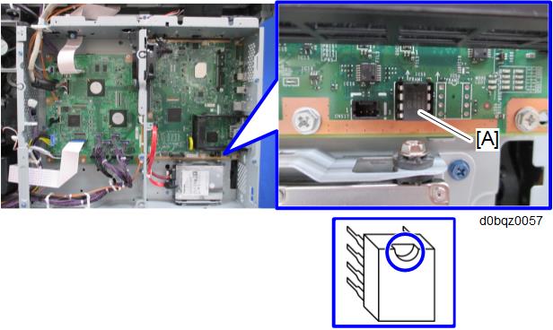
Mounting position and orientation of the NVRAM
- Make sure that you have the SMC report (factory settings). This report comes with the machine.
- Output all the SMC data using SP5-990-001 (SP Print Mode: All (Data List)), or download the SMC data to an SD card using SP5-992-001 (SP Text mode: ALL (Data List))
Make sure to shut down and reboot the machine once before printing/exporting the SMC. Otherwise, the latest settings may not be collected when the SMC is printed/exported. - Turn the main power switch OFF.
- Insert an SD card into Slot 2 and turn the main power switch ON.
- Upload the NV-RAM data on the controller board to the SD card using SP5-824-001 (NV-RAM Data Upload).
Make sure that the customer has backed up their Address Book data. If they have not, save the Address Book data to an SD card using SP5-846-051 (Backup All Addr Book).

- The address data stored in the machine will be discarded later during this procedure. So be sure to obtain a backup of the customer’s address book data.
- Note that the counters for the user will be reset when doing the backup/restore of the address book data.
- If they have a backup of the address book data, use their own backup data for restoring. This is because there is a risk that the data cannot be backed up properly depending on the NV-RAM condition.
- Do the following steps if the machine has the fax unit. If not, skip this step:
- Print the Box List with the Settings.
- [Settings] - [Facsimile Settings] - [General Settings] - [Box Setting: Print List]
- Print the Special Sender List by pressing these buttons in the following order.
- [Settings] - [Facsimile Settings] - [Reception Settings] - [Program Special Sender: Print List]
- Write down the following fax settings.
- [Receiver] in [Settings] - [Facsimile Settings] - [Reception Settings] - [Reception File Settings] - [Forwarding].
- [Notify Destination] in [Settings] - [Facsimile Settings] - [Reception Settings] - [Reception File Settings] - [Store].
- [Specify User] in [Settings] - [Facsimile Settings] - [Reception Settings] - [Stored Reception File User Setting].
- [Notify Destination] in [Settings] - [Facsimile Settings] - [Reception Settings] - [Folder Transfer Result Report].
- Specified folder in [Settings] - [Facsimile Settings] - [Send Settings] - [Backup File TX Setting].
- [Receiver] in [Settings] - [Facsimile Settings] - [Reception Settings] - [Reception File Settings] - [Output Mode Switch Timer].
- [Store: Notify Destination] in [Settings] - [Facsimile Settings] - [Reception Settings] - [Output Mode Switch Timer].
- All the destination information shown on the display.

- In the fax settings, address book data is stored with entry IDs, which the system internally assigns to each data. The entry IDs may be changed due to re-assigning in backup/restore operations.
- Make sure that there is no transmission standby file. If any standby file exists, ask the customer to delete it or complete the transmission.
- Print the Box List with the Settings.
- Turn the power OFF and unplug the power supply cord.
- Push the power switch ON again to discharge the residual charge.
- Replace the NV-RAM with a brand-new one.
Turn the power ON with the SD card to which the NV-RAM data has been uploaded in Slot 2.
- SC673 appears at start-up, but this is normal behavior. This is because the controller and the smart operation panel cannot communicate with each other due to changing the SP settings for the operation panel.
- Change the SP settings for the operation panel.
If you switch the screen to enter the SP mode, SC995-02 is displayed. However, continue the following steps.- SP5-748-101: (OpePanel Setting: Op Type Action Setting): Change bit 0 from 0 to 1.
- SP5-748-201: (OpePanel Setting: Cheetah Panel Connect Setting): Change the value from 0 to 1.
- Change the Flair API SP values.
- SP5-752-001 (Copy FlairAPIFunction Setting): Change bit 0 from 0 to 1.
- SP1-041-001 (Scan:FlairAPI Setting): Change bit 0 from 0 to 1.
- SP3-301-001 (FAX:FlairAPI Setting) Change bit 0 from 0 to 1.
Cycle the power OFF/ON.
- The model information is written on the NVRAM (Novita), so SC995-02 does not occur.
- Program/Change Administrator will be displayed in Japanese, but this is normal.
- Enter the SP mode and specify the following settings manually.
- a. SP5-985-001 (Device Setting: On Board NIC) Change the value from 0 to 1.
- b. SP5-985-002 (Device Setting: On Board USB) Change the value from 0 to 1.
- Turn OFF the main power, and then turn ON the main power with the SD card to which the NV-RAM data has been uploaded in Slot 2.
Download the NV-RAM data stored in the SD card to the brand-new NV-RAM using SP5-825-001 (NV-RAM Data Download).
- The download will take a couple of minutes.
- Turn the power OFF and remove the SD card from slot 2.
- Turn the power ON.
The screen "Program/Change Administrator" will be displayed in the language that is the same language as the time when the data was uploaded to the SD card in step 5. - Execute SP5-755-002 (Hide Administrator Password Change Scrn).
After you execute this SP and exit SP mode, the Home screen is displayed and user functions can be used. - If the security functions (e.g. Stored file encryption/ Auto Erase Memory Setting) were applied, set the functions again.
Ask the customer to restore their address book. Or restore the address book data using SP5-846-052 (UCS Setting: Restore All Addr Book), and ask the customer to ensure the address book data has been restored properly.
- If you obtained the backup of the customer’s address book data in step 3, delete the backup immediately after the NV-RAM replacement to avoid accidentally taking out the customer’s data.
Output all the SMC data with SP5-990-001 and make sure all the SP/UP settings except for counter information are properly restored, by checking the SMC data obtained in step 2.
- The counters will be reset.
- When equipped with fax, make sure that the list printed in steps 7-1 to 7-2 are the same as the sender information that you wrote down in step 7-3.
If the setting is different from the original setting after the replacement of the NVRAM, then set it again to the original setting. - Execute the process control (SP3-011-001).
- Execute the ACC (Copy).
- Execute the ACC (Printer).
- Cycle the power OFF/ON.
- If you cannot execute SP5-824-001 or SP5-825-001 for some reason, try all the following things.
- Check the changed SP value on the SMC which was output in step 2 and set it manually. Especially, ensure that the values of the following SPs are same as the setting before the replacement.
- a. SP5-045-001 (Accounting counter: Counter Method)
- b. SP5-302-002 (Set Time: Time Difference) - Because the PM counters have been reset during NV-RAM replacement, it is necessary to replace all the PM parts for proper PM management.
- If a message tells you need a SD card to restore displays after the NV-RAM replacement, create a "SD card for restoration" and restore with the SD card.
SP descriptions
- 5-846-051 (UCS Setting: Backup All Addr Book)
Uploads all directory information to the SD card. - SP5-748-201 (OpePanel Setting: Cheetah Panel Connect Setting)
0: OFF
1: ON - SP5-752-001 (Copy: FlairAPIFunction Setting)
Sets Copy FlairAPI Function enable / disable. - SP1-041-001 (Scan: FlairAPI Setting)
Sets Scanner FlairAPI Function enable / disable. - SP3-301-001 (FAX: FlairAPI Setting)
Sets Fax FlairAPI Function enable / disable.
Bit Switches for FlairAPI Settings
Bit | Item | 0 | 1 | Description | Initial value |
|---|---|---|---|---|---|
0 | Flair API Server Boot | Disabled | Enabled | Specifies whether to start the HTTP server for Flair API. "0" disables all the Flair API functions (Remote UI). | 0 |
1 | Access Permission | Enabled | Disabled | Setting this value to “0” permits only internal access in the machine (MFP browser). Setting this value to “1” permits to access from external devices such as PC, Remote UI, IT-BOX. | 0 |
2 | Select IPv6/IPv4 | IPv6 | IPv4 | Setting this value to “0” permits only accessing with IPv6. Setting this value to “1” permits accessing with IPv4 or IPv6. | 0 |
3 | Remote UI | Not use | Use | Sets whether to use the Remote UI. | 0 |
4 | Reserved | - | - | N/A | N/A |
5 | Reserved | - | - | N/A | N/A |
6 | Reserved | - | - | N/A | N/A |
7 | Reserved | - | - | N/A | N/A |
- SP5-985-001/002 (Device Setting: On Board NIC/On Board USB)
The NIC and USB support features are built into the GW controller. Use this SP to enable and disable these features. In order to use the NIC and USB functions built into the controller board, these SP codes must be set to "1". - SP5-824-001 (NV-RAM Data Upload)
Uploads the NVRAM data to an SD card. - SP5-825-001 (NV-RAM Data Download)
Downloads data from an SD card to the NVRAM in the machine. - SP5-755-002 (Hide Administrator Password Change Scrn)
Hides the input screen of the administrator password temporarily. - SP5-193-001 (External Controller Info. Settings)
Sets the model of the external controller connected to the main unit.
0: External Controller is not installed
1: EFI
2: Ratio
3: Egret
4: GJ
5: Creo
6: QX-100
7: Kurofune
8 to 10: Reserved - SP5-846-052 (UCS Setting: Restore All Addr Book)
Downloads all directory information from the SD card. - SP5-045-001 (Accounting counter: Counter Method)
Sets the counter methods as follows; Developments, Prints or Coverage. - SP5-302-002 (Set Time: Time Difference)
Adjusts the RTC (real time clock) time setting for the local time zone.
Examples: For Japan (+9 GMT), enter 540 (9 hours x 60 min.)
Japan: +540 (Tokyo)
NA: -300 (New York)
EU: + 60 (Paris)
CHN: +480 (Beijing)
TWN: +480 (Taipei)
AA: +480 (Hong Kong)
KO: +540 (Korea)