- Remove the rear cover.
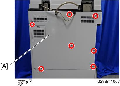
- Remove the rear lower cover.
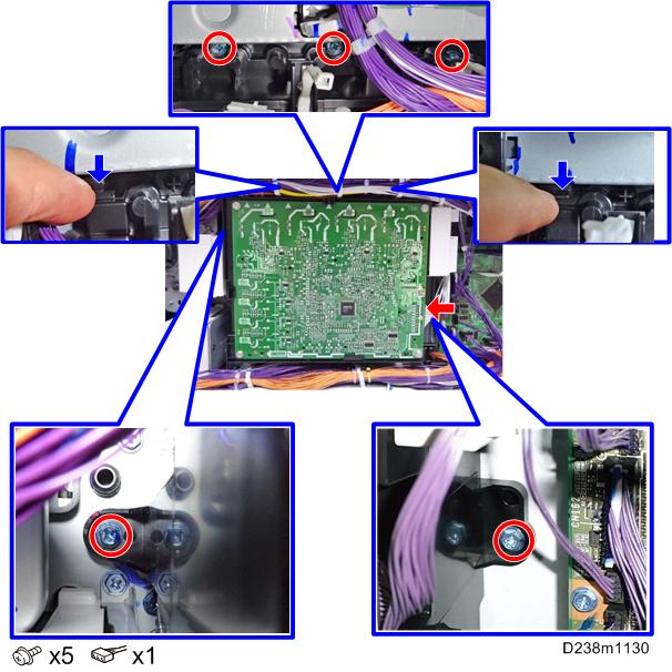
- Remove the power supply box [A] (
 x6, among them, tapping screw x1).
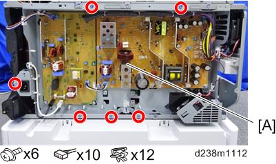
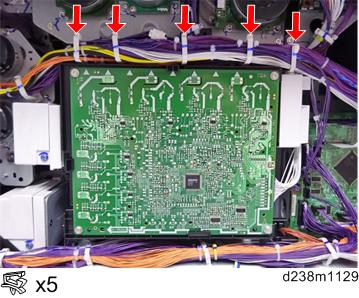
- Release the 5 clamps.
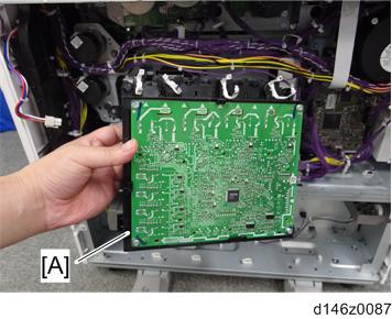
- Remove the HVP-CB (PCB19) with bracket [A] (Hook x2).
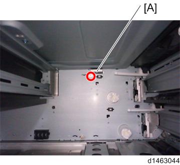
Connect the combined Blue/White harness to the back frame [A].
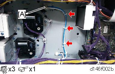

- The harness will be connected to the relay board. See the details in step 8.
- Reinstall the HVP-CB unit and power supply box.
- Secure the relay board to the main machine and connect the Blue/White harness to the connector on the board (
 × 1, × 3).
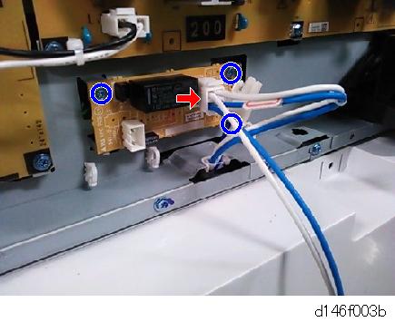
Connect the harnesses on the relay board to the connectors on the PSU.
- Two types of harnesses are packed with the heater. Both the Blue/White one [A] and the Gray one [B] must be connected as shown below.
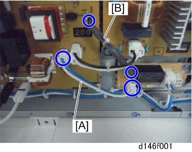
- Two types of harnesses are packed with the heater. Both the Blue/White one [A] and the Gray one [B] must be connected as shown below.
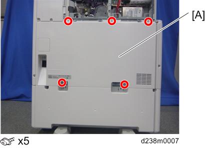
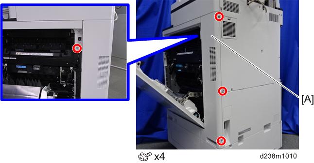
- Remove the right rear cover [A] (x4, among them, tapping screw x1).
- Remove a screw.
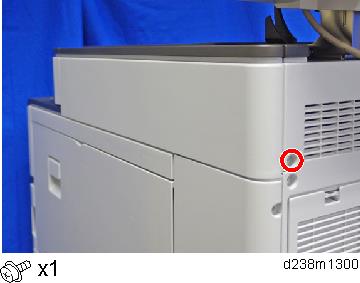
- Remove the scanner right cover [A].
Remove the hook at the upper part, and then slide the cover in the rear direction.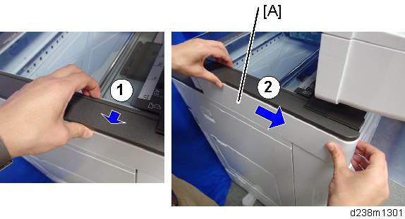
- Route the harness around the outside of the PSU and pull the harness out of the electrical box through the hole [A] (
 x 4).
x 4).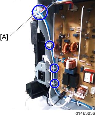
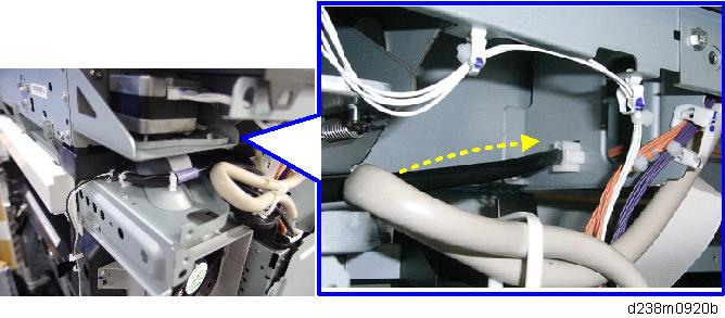
Route the harness in the direction of the scanner (
x 6).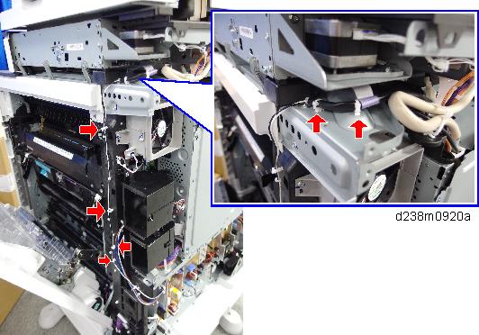

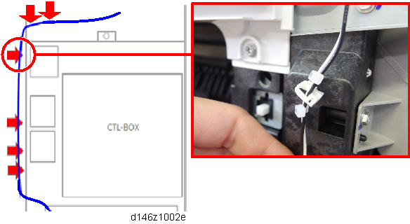
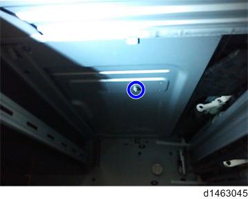
- Fasten the clamp between the bindings of the harness at the location indicated by the red circle.
- Fasten the clamp between the bindings of the harness at the location indicated by the red circle.
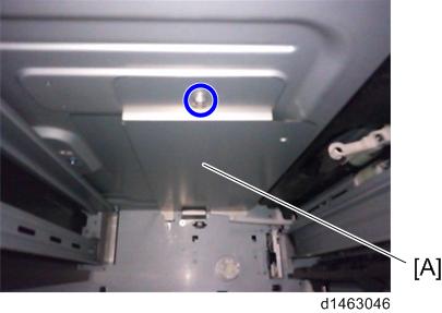
- Attach the connector to the frame.
- Remove Feed Trays 1 and 2.
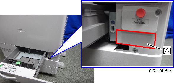
- The connector cover located inside the machine [A] ( × 1).
- Temporarily tighten a screw at the top (M3x8: x1).
Install the heater [A] by connecting the connector to the inside of the machine, then tighten the screw completely.
- Hold the heater against the inside during final tightening.
- Reinstall the connector cover ( × 1).
- Attach the warning decal [A].
- Reassemble the machine.
- Connect the power cord, and then check that the heater is being powered and heated.