- Remove the exposure glass. (Exposure Glass)
- Remove the scanner front cover. (Scanner Front Cover)
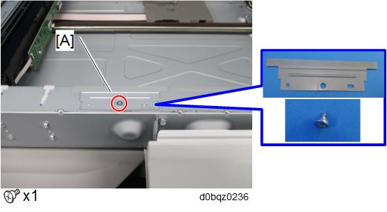
- Remove the scanner carriage front cover [A].
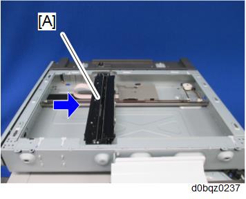
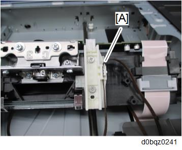
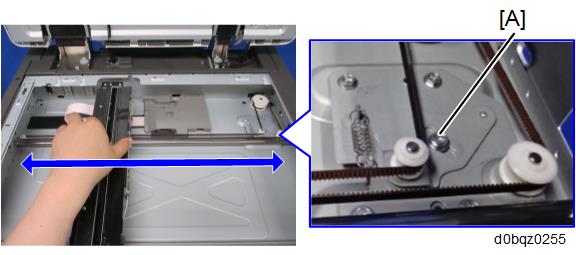
- Move the scanner carriage [A] to the indicated position as shown.
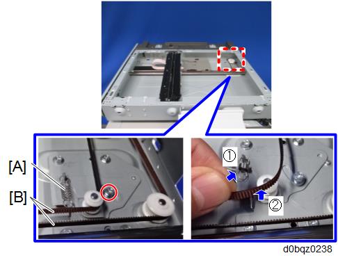
- Loosen the screw, remove the spring [A], and then remove the belt [B].
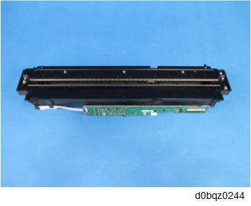
Turn the scanner carriage over and place it on the frame [A].
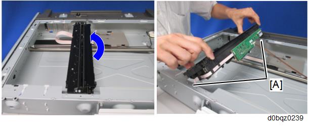

- When holding the scanner carriage, be careful not to touch the circuit board [A], lens [B], and mirror [C].
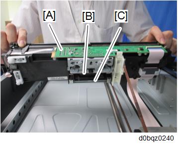
- When holding the scanner carriage, be careful not to touch the circuit board [A], lens [B], and mirror [C].
- Remove the Belt [A].
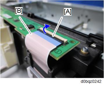
- Lower the lock lever [A] and disconnect the FFC [B].
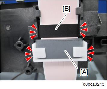
- Remove the ferrite core [A] and the sheet [B] (Hook x4).
- Remove the scanner carriage.
- When attaching the scanner carriage, hold the carriage with the screw [A] loosened and move the carriage back and forth to the sides twice to have the belt stretch evenly. Then, fasten the screw [A].
- After replacing the scanner carriage, enter the values supplied with the carriage in the following SP
- SP4-871-002 (Distortion Correction Distortion Initialization)
- SP4-880-001 (Dot shift amount between R Line and G Line).
- SP4-880-002 (Dot shift amount between G Line and B Line).
To apply the specified settings, turn the power off and then back on.
The specified values are cleared when the NVRAM is initialized, so be sure to keep the supplied sheet showing the values in the machine.