In the following diagrams, solid lines represent "K" and dotted lines indicate any of "C", "M" or "Y".
- Pattern 1
This is a case in which there is a shift in the sub-scan direction at the leading edge of the paper. The following diagram shows "C", "M" or "Y" lines closer to the leading edge than "K" lines.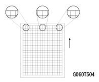
- Pattern 2
This is a case in which there is a shift in the sub-scan direction at the trailing edge of the paper. The following diagram shows "C", "M" or "Y" lines farther away from the leading edge than "K" lines.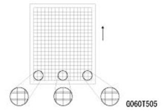
- Pattern 3
This is a case in which a color registration error is found in the main-scan direction and size of the error is the same at the left, center and right.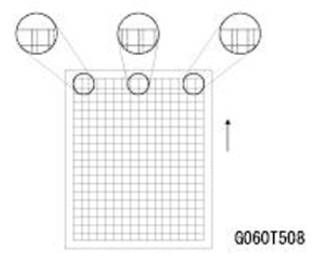
- Pattern 4
This is a case in which a color registration error is found in the main-scan direction and the size of the error is different at the left, center and right. For "M", the largest error will be at the right, followed by the center and then the left. For "C" or "Y", the order will be reversed. This is because the writing direction of the laser beam for "K" and "M" is different from "C" and "Y".
Case "M"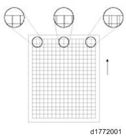
Case "C" or "Y"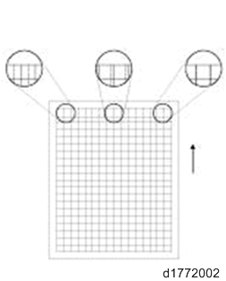
- Pattern 5
This is a case in which a color registration error is found in the sub-scan direction, but it is not the same as the Pattern 1 or 2. The error appears and disappears at intervals down the page.
Ways to fix color registration errors
SP2-111-004 (Forced Line Position Adj. : Mode D) Execution | ||
Result: Failed Case: SP2-194-007: 1 (Failed) | ||
SP2-194-010, 011, 012 shows "2" or "3" | Result of Check | Blank image, abnormal image, low image density |
Causes | 1. Image Processing failure 2. Pattern density low 3. BICU failure | |
Solution | 1.Replace PCU, Intermediate Transfer Belt, Power pack 2. Execute process control, supply toner 3. Replace the BICU (PCB10) | |
Pattern | - | |
Failed to read the pattern of Line position Adj. | Result of Check | Normal (but color registration errors occur) |
Causes | 1. ID Sensor failure 2. BICU failure | |
Solution | 1. Replace the TM/ID Sensor (S48) 2. Replace the BICU (PCB10) | |
Pattern | - | |
Any of SP2-194-010 or 011 or 012 shows "5"
| Result of Check | Image density low |
Causes | Pattern density low | |
Solution | Execute the process control Supply toner | |
Pattern | - | |
Any of SP2-194-010 or 011 or 012 shows "5"
| Result of Check | Leading edge registration for "M", "C", and/or "Y" shifts over ±1.4mm from that of "K". |
Causes | 1. Laser unit failure 2. BICU failure | |
Solution | 1. Execute SP2-111-003 (Forced Line Position Adj.: Mode c) 2. Replace Laser unit 3. Replace the BICU (PCB10) | |
Pattern | 3 | |
Out of line position correction range | Result of Check | Leading edge registration of "M", "C", and/or "Y" shifts over ±1.4mm from that of "K". |
Causes | 1. Normal 2. Image Transfer Belt failure 3. Drive Section failure 4. BICU failure | |
Solution | 1. Execute SP2-111-003 (Forced Line Position Adj.: Mode c) 2. Replace Image Transfer Belt 3. Replace PCU/Drum motor 4. Replace the BICU (PCB10) | |
Pattern | 1, 2 | |
Result of Check | The main scan magnification is OK, but the color registration in the center of the image shifts over 0.66mm. | |
Causes | 1.ID Sensor(Center) failure 2. Significant movement of Image Transfer Belt (Center) 3.BICU failure | |
Solution | 1. Replace the TM/ID Sensor (S48) 2. Replace Image Transfer Belt 3. Replace the BICU (PCB10) | |
Pattern | - | |
Out of line position correction range | Result of Check | Skew of "M", "C" and/or "Y" shifts over ±0.75mm against that of "K" |
Causes | 1. PCU installation failure 2. Laser Unit failure 3. BICU failure | |
Solution | 1. Reset/Replace PCU 2. Replace Laser Unit 3. Replace the BICU (PCB10) | |
Pattern | - | |
Result of Check | Other | |
Causes | 1. The upper skew correction value is abnormal 2. BICU failure | |
Solution | 1. Reset skew correction value (*1) 2. Replace the BICU (PCB10) | |
Pattern | - | |
*1 Method for resetting the skew correction value.
- Turn the power OFF.
- Remove the left cover. (Left Cover)
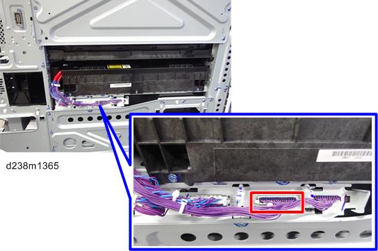
- Remove the harness of the laser optics positioning motor (M23) (M24) (M25) attached to the laser unit (15-pin).
- Turn the power ON, and then execute the following SPs to set the skew correction mechanism to the origin.
SP2-220-001 (Skew Origin Set M: Skew Motor)
SP2-220-002 (Skew Origin Set C: Skew Motor)
SP2-220-003 (Skew Origin Set Y: Skew Motor) - Turn the power OFF.
- Connect the harness of the skew correction motor to the laser unit.
- Turn the power ON.
SP2-111-001 (Forced Line Position Adj.: Mode A) execution (or Color Registration via the Maintenance menu in Settings) | ||
Result: OK Case: SP2-194-007: 0 (Success) | ||
No color registration errors | Result of Check | Side-to-side registration for K shifted |
Causes | Abnormal SP value of main scan color registration (K) | |
Solution | Adjust SP2-101-001 | |
Pattern | - | |
Color registration errors found | Result of Check | Image density low |
Causes | Pattern density low | |
Solution | Execute process control, Supply toner | |
Pattern | - | |
Color registration errors found | Result of Check | The main scan magnification of "M", "C" and/or "Y" is not correct. |
Causes | 1. Laser Unit failure 2. ID Sensor failure 3. BICU failure 4. Normal | |
Solution | 1. Replace Laser Unit 2. Replace the TM/ID Sensor (S48) 3. Replace the BICU (PCB10) | |
Pattern | 4 | |
Color registration errors found | Result of Check | Although main scan magnification is OK, the color registration in the center of the image is shifted |
Causes | 1. Significant movement of Image Transfer Belt (Center) 2. ID Sensor (Center) failure 3. BICU failure | |
Solution | 1. Replace Image Transfer Belt 2. Replace the TM/ID Sensor (S48) 3. Replace the BICU (PCB10) | |
Pattern | - | |
Color registration errors found | Result of Check | The side-to-side registration of "M", "C", and/or "Y" is not correct. |
Causes | 1.ID Sensor(Center) failure 2. Significant movement of Image Transfer Belt (Center) 3. BICU failure | |
Solution | 1. Replace Laser Unit 2. Replace the TM/ID Sensor (S48) 3. Replace the BICU (PCB10) | |
Pattern | 3 | |
Color registration errors found | Result of Check | The leading edge registration of "M", "C" and/or "Y" is not correct. |
Causes | 1. Image Transfer Belt failure 2. Drive Section failure 3. ID Sensor failure 4. BICU failure 5. Normal | |
Solution | 1. Replace Image Transfer Belt 2. Replace PCU, Drum motor 3. Replace the TM/ID Sensor (S48) 4. Replace the BICU (PCB10) | |
Pattern | 1, 2 | |
Color registration errors found | Result of Check | The skew of "M", "C" and/or "Y" is not correct. |
Causes | 1. PCU installation failure 2. Laser Unit failure 3. IOB failure | |
Solution | 1. Reset/Replace PCU 2. Replace Laser Unit 3. Replace IOB | |
Pattern | - | |
Color registration errors found | Result of Check | Shifted Drum phase. |
Causes | 1. PCU installation failure 2. Drive Section failure 3. Phase adjustment failure | |
Solution | 1. Reset/Replace PCU 2. Check/Replace Drive Section 3. Execute SP1-902-001 | |
Pattern | 5 | |