- Remove the proximity sensor left cover [A].
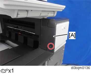
- Open the right door, and then remove the small cover [A].
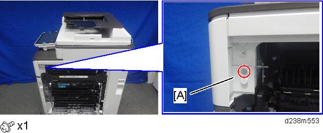
- Open the front cover.
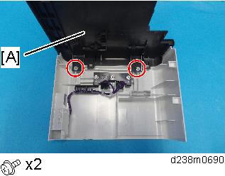
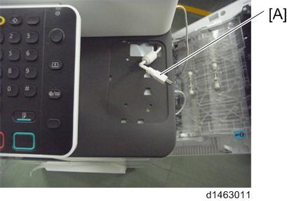
Remove the proximity sensor cover [A].

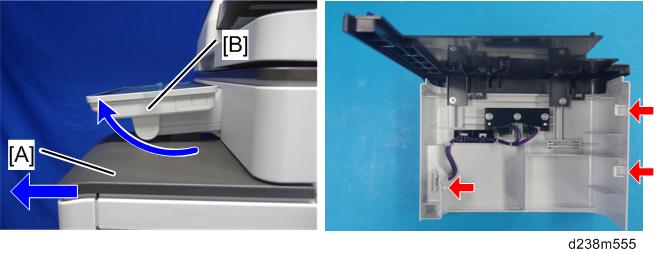
- Remember that there is a tab at the positions of the red arrows.
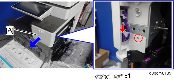
- Rotate the operation panel [B] upward to a horizontal position, and then detach the proximity sensor cover [A].
- Remove the original upper cover [A]
- Attach the corner cover [A] provided with this option.
Use the screws removed in the previous step.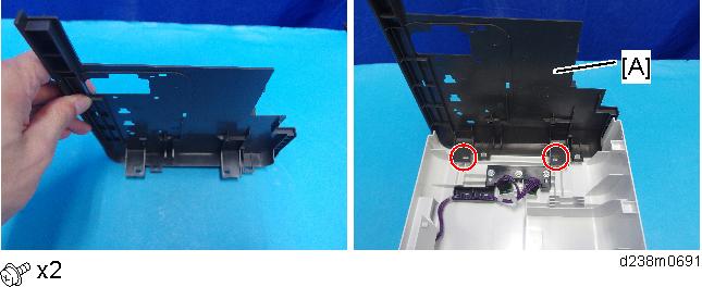
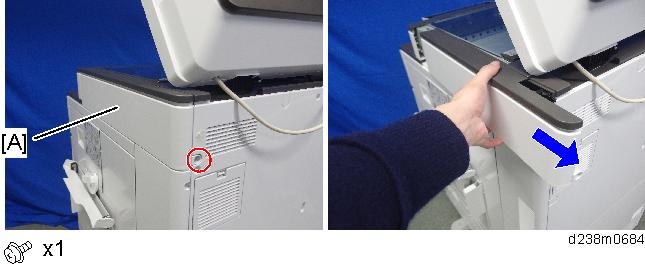
- Remove the scanner right cover [A].
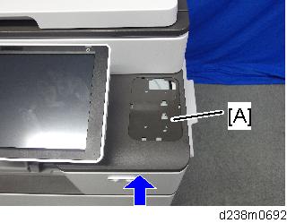
- Reattach the proximity sensor cover with corner cover [A] to the machine.
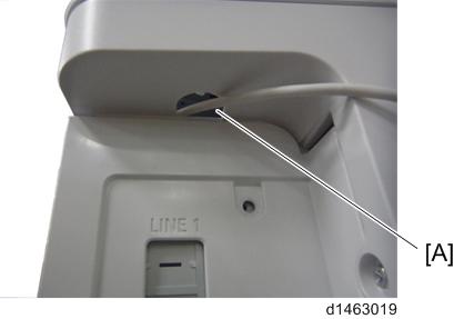
Pass the USB cable [A] through the hole.
- This cable is not included in this unit. The user may need to provide it.
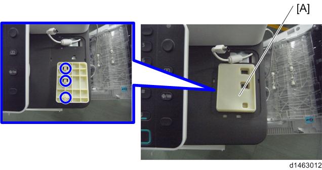
Attach the table [A].
- There are three ribs on the back side of the table.
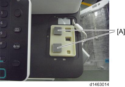
- Attach the sponges [A] with double-sided tape.
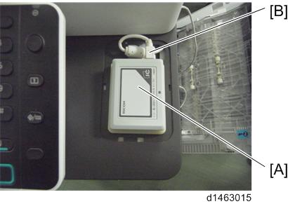
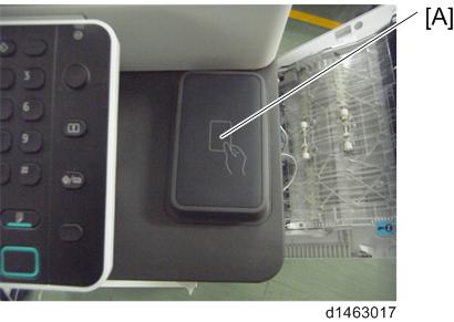
Connect the cable [B] to the IC reader [A] and attach the reader to the table.
- The USB cable should be turned as the following photo shows.
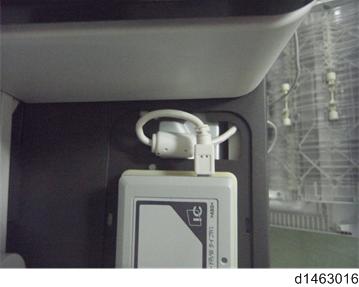
- The USB cable should be turned as the following photo shows.
- Attach the IC card reader cover [A].
- Attach the three clamps (
 x3).
x3).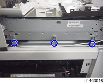
- Remove the cover to make the hole [A] to pass the cable through.
- Connect the USB connector to the USB interface of the controller.

- Route the cable as shown in the following photo (x1).
Tuck in the excess length portion of the cable in the space over the controller box.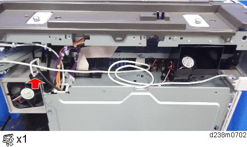
- Reattach the exterior covers.