- When installing this option, turn OFF the main power and unplug the power cord from the wall socket. If installing without turning OFF the main power, an electric shock or a malfunction may occur.

- This option cannot be used together with the following peripherals:
- Internal Shift Tray SH3080 (D3FV)
- Bridge Unit BU3090 (D3FT)
- Internal Finisher SR 3300 (D3FT)
- Internal Finisher SR 3250 (D3FG)
- Side Tray Type M37 (D3FX)
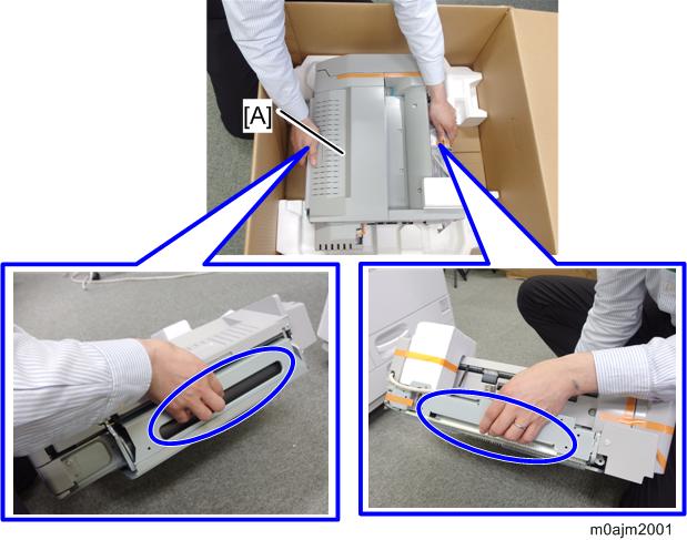
Unpack the internal multi-fold unit [A].
Hold the parts circled in blue. Do not hold other parts. Doing so may damage exterior cover or deform the frame. (Note: The actual packaging tape is blue.)
Remove the packing tapes and retainers, and then remove the accessories (screws, etc.).
There are 2 mylar sheets inside, so be sure to remove them.
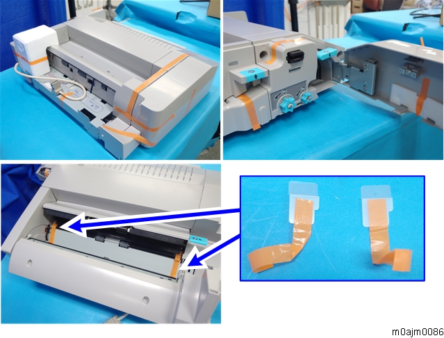
Make sure to remove the tape fixing the joint bracket [A].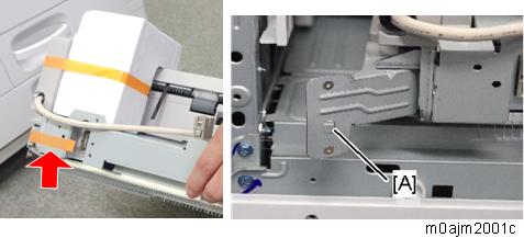
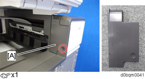
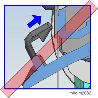
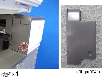
- Remove the proximity sensor left cover [A].
Remove the paper exit feeler [A].
The removed paper exit feeler can be discarded.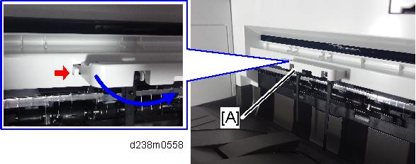
Tuck in the lever [A] for detecting when the tray is full.
Remove the paper exit tray [A].
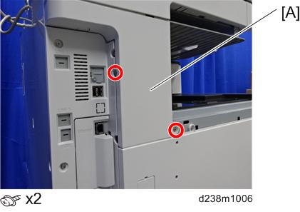
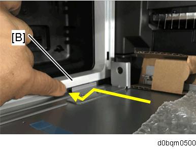
- Remove the connector cover [A].
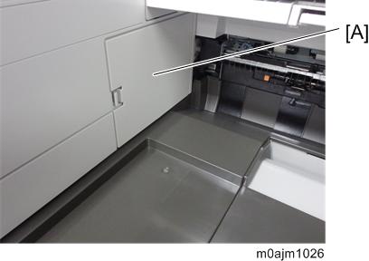
- Remove the upper left cover [A] by pulling it towards the front.
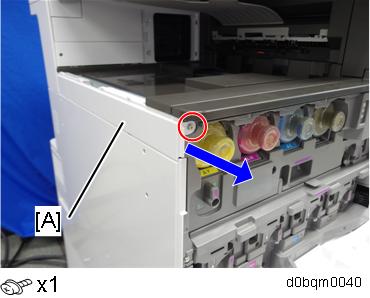
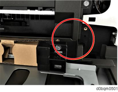
Remove the left rear cover [A].
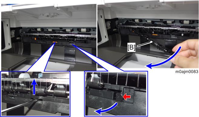
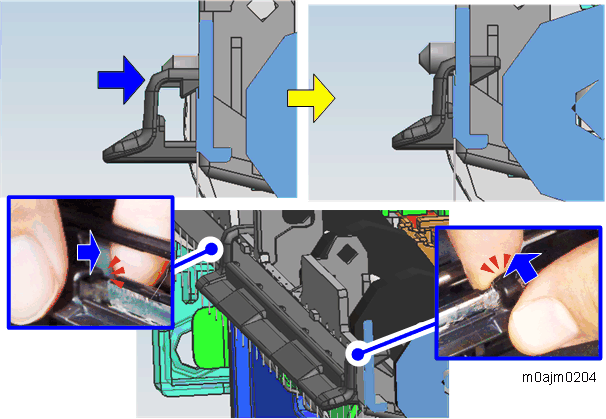
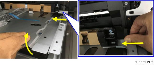
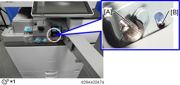
Remove the driven roller [B] at the machine’s exit tray and attach the supplied driven roller [A].
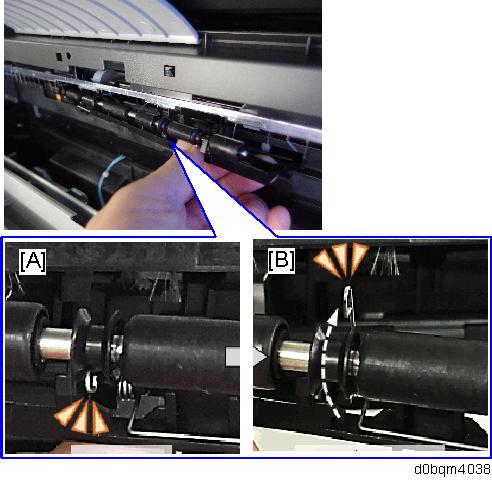
- Insert a flathead screwdriver into the depression in the center, and then, lifting the driven roller, unlock the part indicated by the red arrow.
- When attaching the driven roller, push its center all the way in until it clicks.
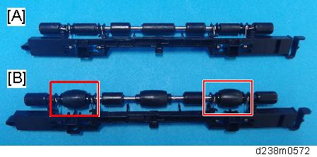
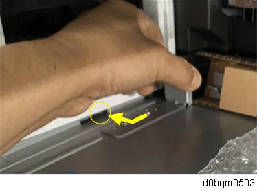
[A]: The supplied driven roller has flat rollers.
[B]: The machine’s standard driven roller has drum-type rollers (as indicated by the red frames).
The spring arm on the flat roller might be disconnected due to the vibration or shock. After attaching the roller, perform a visual check whether the state of assembly is normal or not.
[A]: Normal position, [B]: spring arm is disconnected.
Attach the paper support guide (small) to the exit tray (hook x2).
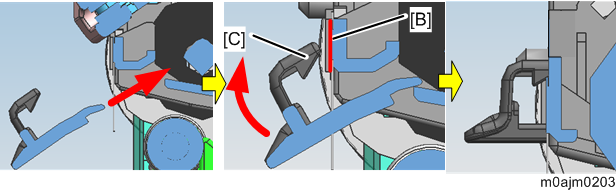
- Align and insert the support guide’s tabs under the notches in the discharge brush frame [A] upward at an angle.
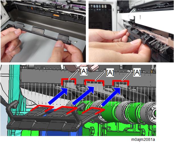
Rotate the support guide upward so that the support guide’s hooks [C] become horizontal to the discharge brush frame [B].
- Do not continue to hold the support guide at an angle when pushing it in. Otherwise, you damage the attachment or the hooks.
- Do not continue to hold the support guide at an angle when pushing it in. Otherwise, you damage the attachment or the hooks.
- Holding the back of the discharge brush frame with the forefingers, push the hooks in horizontally one at a time until they click.
- Align and insert the support guide’s tabs under the notches in the discharge brush frame [A] upward at an angle.
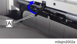
Remove the paper exit lower cover [A].
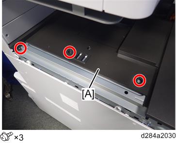
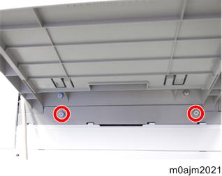
Attach the bottom plate (3 × 6). Before you attach it, insert the bottom plate’s 2 tabs [A] into the slots in the machine.
You can easily install the plate as follows:Evenly insert the bottom plate under the upper rear inner cover [B] from the front.
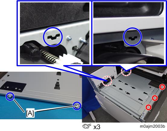
Check that the front resin part of the bottom plate and the paper exit cover are at this location.
Slightly lifting the front right part of the bottom plate, slide the front resin part of the bottom plate under the paper exit cover.
Pulling the bracket at the rear part slightly, engage the hook on the bottom plate with the hole in the side of the machine.
- Reattach the proximity sensor on the left cover.
- Close the front cover.
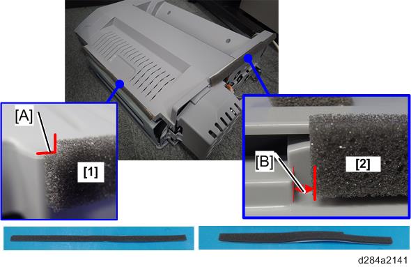
Attach the cushions to the internal multi-fold unit.
When attaching the cushion (paper entrance) [1], align the cutout [A] with the top of the upper cover.
When attaching the cushion (rear) [2], align it with a point 3 mm from the left edge [B].
Open the front cover of the internal multi-fold unit, and then secure the 2 screws in the recesses.
- This operation is required to apply pressure to the internal multi-fold unit roller when attaching it. The screw holes become inaccessible when the unit is attached to the machine, so be sure to perform this in advance.
- Be sure to turn the screws until they stop. It is not necessary to continue tightening them.
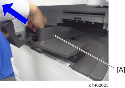
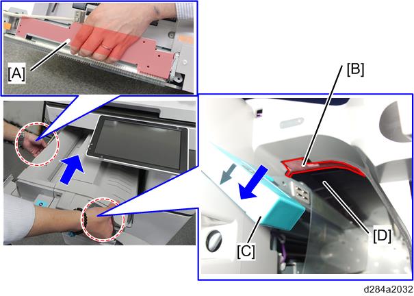
Temporarily place the internal multi-fold unit [A] on the bottom plate.
Open the front cover of the internal multi-fold unit, and then, holding the exit tray frame [A] and the top edge of the opening [B], lift the internal multi-fold unit and attach it to the machine.
- Lower the lever [C] to keep the paper guide plate open during operation, because the plate might be deformed if a strong force is applied while the guide plate is closed.
- Hold the metal frame part of the opening [B], not the exterior cover, to avoid the deformation of the cover.
Be careful not to touch the mylar sheet [D] located behind.
- Be careful not to let the securing bracket [A] get caught between the internal multi-fold unit and the machine.
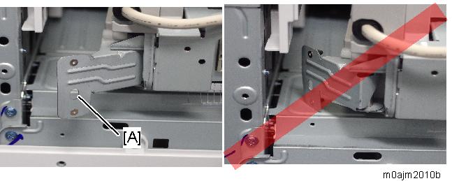
- Be careful not to let the securing bracket [A] get caught between the internal multi-fold unit and the machine.
Attach the securing bracket [A] (M4x6).
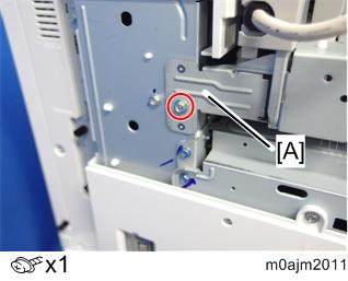
Temporarily attach the internal multi-fold unit with the supplied coin screw (M4x1).
- The unit is only temporarily attached at this stage, so leave the screws loose.
- Fix the screw to the left screw hole [A] of the two screw holes. Do not use the right screw hole [B].
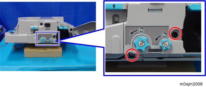
Attach the correction plate for side-to-side registration [A] to the machine (M3x6).
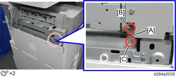
- Partially secure the adjusting screw [B] on the upper part of the correction plate, and then secure the screw [C] at the bottom part of the plate.
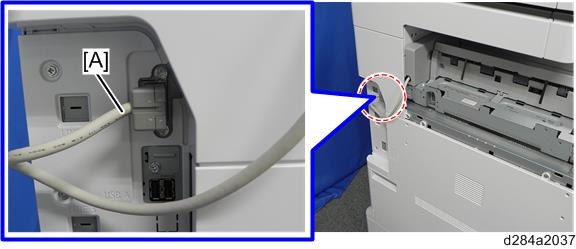
Connect the cable [A] of the internal multi-fold unit to the machine.
Turn ON the main power.
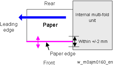
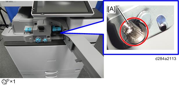
- Feed A3/DLT paper (any brand) from Tray 2 and check the scale [A].
Select the [Settings] icon > [Machine Features Settings] > [Printer Settings] > [List/ Test Print] > [Operation Test].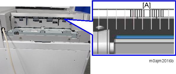
Check the movement at the paper edge from the leading to trailing edges, and turn the adjusting screws of the correction plate to adjust the internal multi-fold unit’s position until the deviation stays within 2 marks on the scale. (Each mark represents 1 mm.)
[A]: When the paper edge shifts towards the front, turn the adjusting screw clockwise.
[B]: When the paper edge shifts towards the rear, turn the adjusting screw counterclockwise.
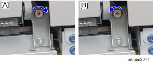
After registration, tighten the coin screw [A] to secure the internal multi-fold unit.
- When you fully open the front cover of the internal multi-fold unit, it may interfere with the machine’s upper front cover, causing the internal multi-fold unit to become misaligned. Therefore, tighten the screw [A] with a stubby screwdriver.
Reattach the left rear cover.
- When attaching the finisher beyond the internal multi-fold unit, attach the supplied paper exit guide (No.9). For details, refer to When Attaching the Finisher Beyond the Internal Multi-Fold Unit.
Reattach the left upper cover.
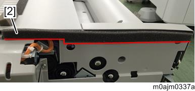
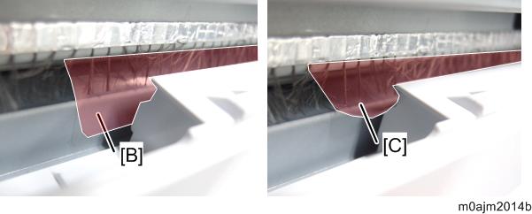
The exit tray of the internal multi-fold unit has mylar sheets [A] on it. When attaching the cover, be careful not to damage the mylar sheets [A].
The left upper cover bulges slightly because of the mylar sheets, but this does not cause any problem if the mylar sheets are positioned correctly.
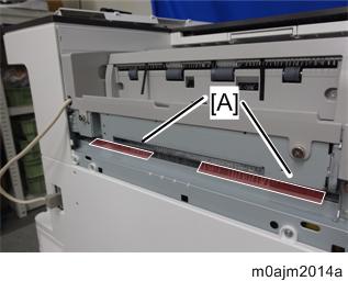
- Reattach the left upper cover with the mylar sheets [B] sandwiched behind it. The mylar sheets must not catch on or hang over the left upper cover, as shown by [C].
- Reattach the inverter tray.
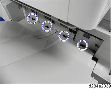
- Insert the 4 hooks on the paper exit tray [A] into the slots (hook x 4).
When attaching the paper exit tray, do not put the movable plate [B] under the paper exit tray, because that would interfere with the operation of the internal multi-fold unit.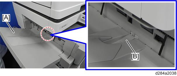
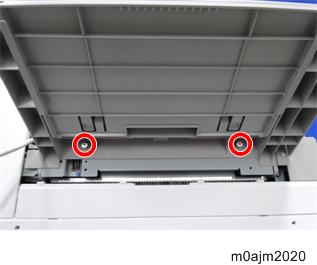
Tighten the screws to secure the paper exit tray (coin screw x2:M4).
Attach the paper relay cover (coin screw x2: M4)